 NOW YOU CAN
TEST:
NOW YOU CAN
TEST:
|
TT-2©
Universal Transducer Test Set |
[ Home]
[ Chirp Depth Sounder Test Set]
[ Computer Controlled Depth Sounder Test Set]
[ Low Frequency Universal Transducer Test Set]
[ Universal Transducer Test Set]
[ Multi Sensor Transducer Test Set ]
[ Computer Controlled Transducer Test Set ]
[ Loran-C Signal Generator ]
NOW YOU CAN
TEST:
 Extended
Frequency Range Load
Reactance Indicator Load
Current Meter Leakage
Indicator Variable
Zout Control
Extended
Frequency Range Load
Reactance Indicator Load
Current Meter Leakage
Indicator Variable
Zout Control
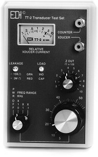
How it Works
The TT-2 sends a signal through a variable resistor connected
to the xducer jack. The voltage at the attached transducer is
monitored and compared to the voltage generated internally in the TT-2.
This voltage difference is converted to current and displayed on the relative
xducer current meter. The phase difference is monitored and drives
a load indicator. At a given frequency, if the load indicator
is red, it means the transducer is capacitive. A green load
indicator shows the transducer to be inductive. At resonance, the
indicator will be dim or off as the transducer is mainly resistive with
negligible reactance. The DC resistance of the load is monitored and
drives the leakage indicator. This leakage indicator is green for
resistances less than 3 megohms, and red for a resistance less than 10K
ohms.
Using the TT-2
Connect a transducer to the xducer jack. Turn the power on and rotate
the frequency knob until the meter peaks, indicating a resonant point.
Most sonar transducers have three resonant points. The TT-2 is
so sensitive that the pressure of a finger on the transducer face will
deflect the meter at only one of the three resonant
points. This is normally the operating frequency of the transducer. The
impedance is found by rotating the z out control until the
meter is in the Zo range. The impedance is indicated by the
position of the z out knob.
Test cable and 9 volt battery included!
Please E-Mail edisales@bbginc.com or telephone (757) 366-9211 (within the USA) for more information on EDI's product design services.
Click here to email your questions or comments to EDI.
[ Home ]
[ Chirp Depth Sounder Test Set ]
[ Options for Depth Sounder Test Set ]
[ Computer Controlled Depth Sounder Test Set ]
[ Universal Transducer Test Set ]
 |
Electronic
Devices, Inc.
1708 South Park Court, Chesapeake, VA 23320. Phone (757) 366-9211 |